a pictures worth a thousand words

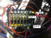
The middle ones are where all of the positive accys should be connected... Pos from the battery should be on the other side of the fuses from them and the last strip is for all negative wires.
 
Sorry guy but that doesn't make spence
You can't put the positive from the battery on all the left side screws
Only one on the top and the ones under on the same side are for the accessories the middle ones are still empty the left is the ground, I would really like to see a pic of one hooked up correct
 
I don't know why you keep saying left and right...the picture I see has "top, middle, and bottom"....

The long silver bar on top is the negative bus. You connect the neg battery and all neg (should be black) accessory wires. [ in the picture, they have incorrectly connect +12v to this bus bar]

The long silver bar on the bottom is the positive bus. You connect the +12v feed from the battery (usually RED). IT SHOULD BE FUSED AT THE BATTERY. And I think in this picture the wire is not heavy enough to feed an accessory bus. That depends on what is connected and how far it is from the battery.[ in the picture, they have incorrectly connect negative battery to this bus bar]

The LOADS in this picture are the orange wires. They should be connected to the middle screws. In that way, they will each get power thru their own fuse.

In this picture, none of the loads are fused. They are connected directly to +12v. The fuses in this picture are not being used at all.
Because they have the +12 and neg bus bars reversed, the fuses will never have power because they are connected to a Negative bus.
It cannot be more wrong.
 

Attachments

  • fuse block.jpg
    fuse block.jpg
    63.9 KB · Views: 19
Last edited:
Sorry guy but that doesn't make spence
You can't put the positive from the battery on all the left side screws
Only one on the top and the ones under on the same side are for the accessories the middle ones are still empty the left is the ground, I would really like to see a pic of one hooked up correct

I'm 'fraid it's you that isn't making sense...

Look at the pic with labels that skunkboat posted... If it still doesn't make sense to you then I'm sorry to say but you need to let someone else take care of your electrical system for you..... Not trying to be mean AT ALL..... just honest.
 
12v Bible For Boats

Had similar worries when I got my v. removed a lot of old wiring that went nowhere, cut off or cleaned up corroded ends, new terminals with heat shrink n seal and changed up from glass fuses to ato/atc fuses in a blue seas panel. The 12 Volt Bible For Boats (latest edition) was a help.
 
energized that crappy system yesterday and went to testing. everything came on and worked except the anchor light. looked at and touched all th wires as best as i could, everywhere that i could. everything actually looked good and nothing was warm, except the anchor light hot wire. it was pretty warm. pulled those two wires. they were both black and very stiff, like automotive wire. sure enough, near the light on the hot wire was a connector where the wire had been spliced. could see corrosion and evidence of arcing. replaced those two with tinned wires. took a closer look at all other wiring and it all looks correct and in good shape. heading out there soon to install my blue seas fuse box, solder and heat shrink all connections and clean up the wire routing. then just add my gps, vhf, second bilge pump and a couple other acc and this phase of the project should be done by lunch tomorrow.
 
I have a 1977 and bought a new negative buss to mount behind the dash and a new positive with spade fuses buss and intend to run the negative black to that buss then the positive red to that buss from the battery and distribute a negative to each electric device from the buss and after the fuse, a red + to each device so it goes through the fuse on the positive, red side. That's the way I remember my big sailboat was wired and I hate those round glass tube fuses. Modern spade fuses are much easier. If my thinking is backward let me know. I have not crawled into the cuddy yet to check it out, just know I want different at this point. I chose to have a separate negative buss which I'll mount and bring one heavy wire from battery to it and then a separate with spade fuses positive (red) buss with a heavy red wire from the battery. From that I will run a black to one side of a switch or device and after the fuse a red to the other side of same switch or device. It's like a loop and the fuse goes into the red side of the loop. I'm quite content with two separate busses unless I've completely forgotten how to do this.
 
Last edited:
basic diagram of what I plan to do

This diagram is how I plan to do mine. The wires in place I will trace with power source and meter/probe, label then run from battery to the busses forward then to each device from the busses through the fuses.
search
 
a simple diagram of what I'll do

This is a clear and simple diagram of what I'll do...if I can upload the photo correctly
 

Attachments

  • wiring2.jpg
    wiring2.jpg
    20 KB · Views: 24
Last edited:
Usually... a new fuse panel has a neg bus already attached.

search for the thread "new dash ideas" or Tag search "Dash" or "electrical"
You'll get some good info, pix, and ideas
 
Last edited:
Also might want to wire in a float switch directly to + side of battery with an inline fuse, so bilge pump is active even with the selector switch in the off position.
 
electric wiring

I had decided not to put a battery switch inline as some haven't with one battery but remembered you can add a simple switch which mounts to the negative battery post and which the negative cable attaches to it. When you want it off to the boat just turn the knob on top and it breaks the connection. Cheap, simple and better than leaving something on inadvertently when you leave the boat for a while and it's not in a slip, etc.
 

Attachments

  • 71269SKmmEL._SL1500_.jpg
    71269SKmmEL._SL1500_.jpg
    25.2 KB · Views: 11
Back
Top